應用:用于各種工業設備
1.最大 26 繼電器輸出.
2.無障礙傳輸距離為 200 米.
3. 最大 4 模擬0-10V輸出通道 (顯示範圍可定製): 撐 2 擴展隔離式數字電位器輸出通道;
4. 2 模擬輸入; 並顯示喺遙控器上, 顯示範圍可定製.
5. 1 急停繼電器輸出常閉觸點.
- 低功耗設計。
- 易於使用。
應用:用于各種工業設備
1.最大 26 繼電器輸出.
2.無障礙傳輸距離為 200 米.
3. 最大 4 模擬0-10V輸出通道 (顯示範圍可定製): 撐 2 擴展隔離式數字電位器輸出通道;
4. 2 模擬輸入; 並顯示喺遙控器上, 顯示範圍可定製.
5. 1 急停繼電器輸出常閉觸點.
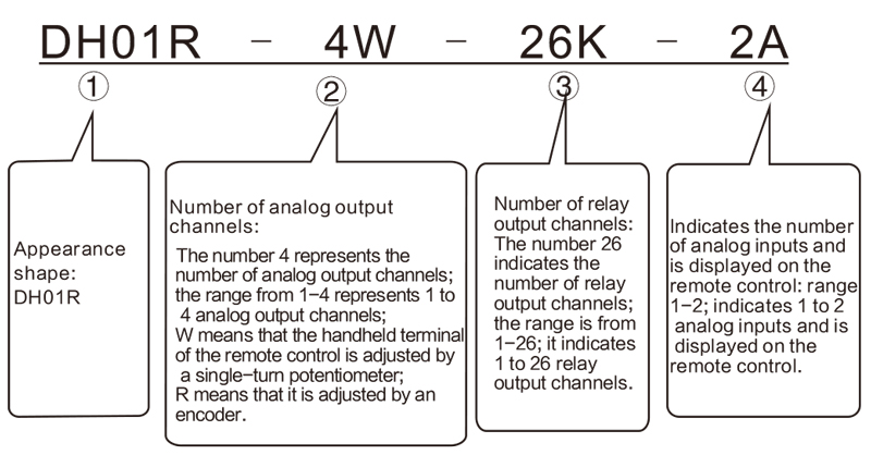
型: DH01R-4W-26K
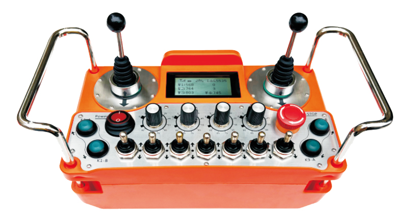
Applicable equipment:various industrial equipment
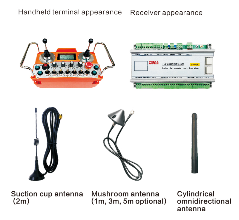
注意: You can choose one of the three antennas. The suction cup antenna is standard by default.
注意:
① DH01R series, if the suffix contains T, it means with emergency stop output;without T, it means without emergency stop output.
②If there is no analog output, there is no need to remark 0W or 0R; the analogquantities W1, W2, W3, and W4 default to 0-10V analog voltage output; at the same time, W1 and W2 can be expanded to 2 isolated digital potentiometer outputs, with a range of 0 -5K ohms, ½ watt; resolution: 20 ohms. The two digital potentials can be used to control the welding current and welding voltage of the welding machine. If the digital potentiometer output is required, user notes are required.
④Analog input, ranging from 1 to 2, indicating that there are 1 to 2 模擬輸入(maximum 2 渠道); when there is an analog input, you need to note the voltage range of the analog input (our receiver defaults to 0 -5V, the user can also note as 4-20 mA or 0-10V, 等。) and the corresponding display range of the analog quantity (for example: display 0-100 volts or 0-1000 amps)
These two analog quantities can be used as displays for welding current and welding voltage.
1)Maximum 26 繼電器輸出;
2)Maximum 4 模擬0-10V輸出通道 (顯示範圍可定製): 撐 2 擴展隔離式數字電位器輸出通道;
3)2 analog inputs; 並顯示喺遙控器上, 顯示範圍可定製
4)1 channels of emergency stop relay output normally closed contacts;
5) Powered by 3 AA電池, low power consumption design;
6) Wireless operation distance is 200 米;
7)Protection grade IP67;
8)With cross switch operation, supports two 4-direction cross switches;
9)Back strap design.
W1 knob value: W1: 0-1000 (parameter adjustable 0-9999)
W2 knob value: W2: 0-5000 (parameter adjustable 0-9999)
W3 knob value: W3: 0-5000 (parameter adjustable 0-9999)
W4 knob value: W4: 0-5000 (parameter adjustable 0-9999)
ADC1 feedback display: 0-1000 (parameter adjustable 0-5000)
ADC2 feedback display: 0-1000 (parameter adjustable 0-5000)
Low voltage: The remote control battery is too low, 請更換電池.
Network dropped: The wireless signal is interrupted. Please check the power of the receiver, power it on again, and restart the remote control.
1) Turn on the remote control
When the receiver is powered on, the receiver working indicator flashes; install two AA batteries in the remote control, turn on the power switch, and the display shows a value,indicating successful startup. The receiver working indicator light becomes solid.
2)Switch and button functions
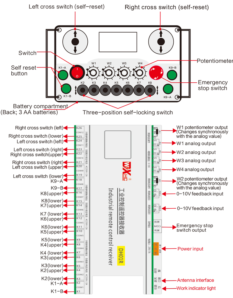
Any operation of the twist switch and button on the remote control can control the corresponding switch signal output point on the receiver. All switch signal output points on the receiver are normally open signals by default;
3)W1-W4 speed adjustment
Rotate the knobs in W1-W4 arbitrarily to operate the corresponding analog output signal or potentiometer signal at the receiver end. The analog output signal at the receiver end defaults to a 0-10V voltage signal, and the potentiometer signal defaults to 0-5K;
4) Emergency stop function
When the emergency stop button is pressed, all switch signal outputs are disconnected and the analog output is disconnected; after the emergency stop is released, all switch signals are restored and the analog output is restored; 5 seconds after the remote control is turned off, all switch signal outputs are disconnected and the analog quantities remain unchanged. When the remote control is turned on, the switch signal outputs automatically recover;
5)Parameter menu (users are prohibited from modifying it privately)
Some functions of the remote control can be adjusted through parameters. When the display W1=0, press the K9-B button 3 times in a row, and then press the K9-A button 3 times in a row to enter the parameter menu; K9-A and K9-B key to page through the menu and select parameters; hold down K1-A, and then press the K9-A/B button to modify parameters;
Exit the parameter menu: choose to save or not save, and then press the K1-A button to confirm the exit;
F1W1 range: The display range value of the W1 knob on the display screen, adjustable from 0 to 9999;
F2W2 range: The display range value of the W2 knob on the display screen, adjustable from 0 to 9999;
F3W3 range: The display range value of the W3 knob on the display screen, adjustable from 0 to 9999;
F4W4 range: The display range value of the W4 knob on the display screen, adjustable from 0 to 9999
F5A1 range: Display ADC1 feedback display range value, 0-5000 adjustable;
F6A2 range: Display ADC2 feedback display range value, 0-5000 adjustable;
Alarm current: Set the alarm value for ADC1 and ADC2 feedback display. When ADC1 and ADC2 exceed this value, the remote control display will alarm; when this value is 0,the alarm function is invalid;
The final interpretation right of this product belongs only to our company.