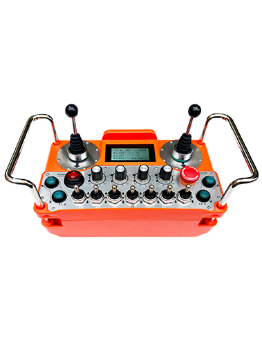
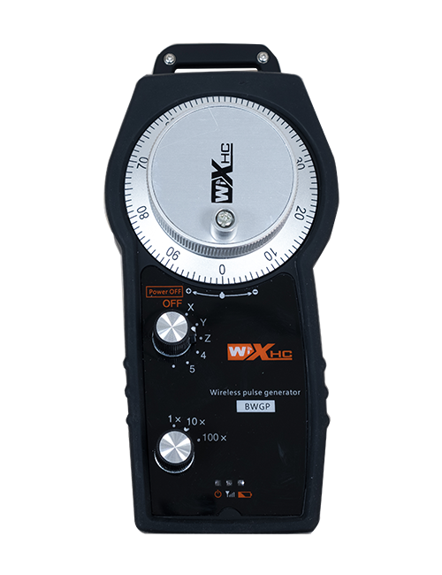
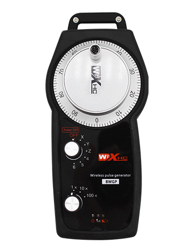
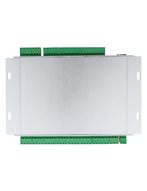
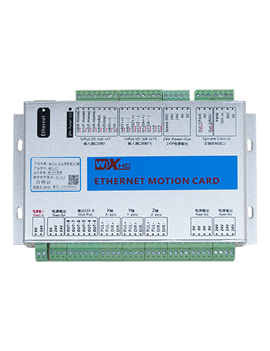
Beskrivning
1.Produktmodell
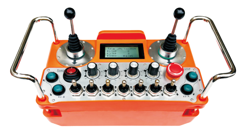
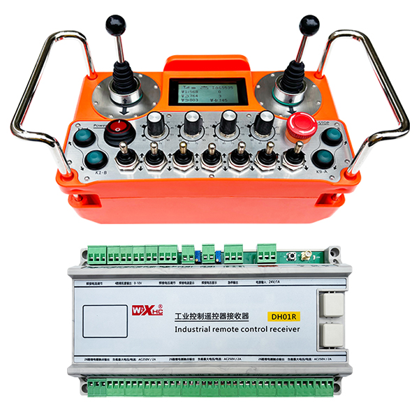
Modell: DH01R-4W-26K
Tillämplig utrustning:Olika industriutrustning
2.Produkttillbehörsdiagram
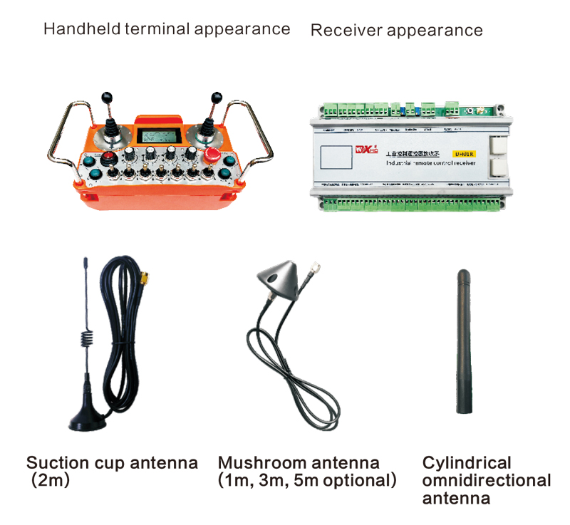
Notera: Du kan välja en av de tre antennerna. Sugskoppantennen är som standard standard.
3.Produktmodellbeskrivning
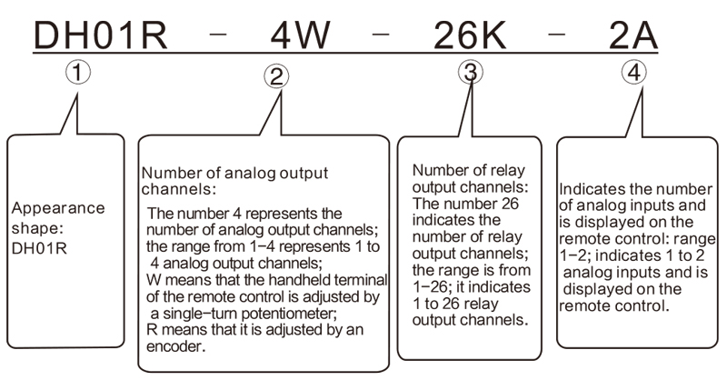
Notera:
① DH01R -serie, Om suffixet innehåller t, Det betyder med nödstoppproduktion;utan t, det betyder utan nödstoppproduktion.
② Om det inte finns någon analog utgång, det finns inget behov av att kommentera 0W eller 0r; analogkvantiteterna w1, W2, W3, och W4 Standard till 0-10V analog spänningsutgång; samtidigt, W1 och W2 kan utvidgas till 2 Isolerade digitala potentiometerutgångar, med en rad 0 -5K ohms, ½ watt; upplösning: 20 ohms. De två digitala potentialerna kan användas för att styra svetsströmmen och svetsspänningen på svetsmaskinen. Om den digitala potentiometerutgången krävs, Användaranteckningar krävs.
④Analog -ingång, allt från 1 till 2, indikerar att det finns 1 till 2 analoga ingångar(maximal 2 kanal); När det finns en analog ingång, Du måste notera spänningsområdet för den analoga ingången (Vår mottagare är standard för 0 -5V, användaren kan också notera som 4-20 MA eller 0-10V, etc.) och motsvarande visningsområde för den analoga mängden (till exempel: visa 0-100 volt eller 0-1000 ampere)
Dessa två analoga mängder kan användas som skärmar för svetsström och svetsspänning.
4.Drag
1)Maximal 26 reläutgångar;
2)Maximal 4 Kanaler med analog 0-10V-utgång (Displayområdet kan anpassas): stödja 2 Kanaler med utökad isolerad digital potentiometerutgång;
3) 2 Analoga ingångar; och visas på fjärrkontrollen, Displayområdet kan anpassas
4) 1 kanaler för nödstopp reläutgång normalt stängda kontakter;
5) Drivs av 3 AA -batterier, Låg effektförbrukning;
6) Trådlös driftsavstånd är 200 mätare;
7) Skyddsklass IP67;
8) Med tväromkopplare, stöder två 4-riktningskorsbrytare;
9) Back Strap Design.
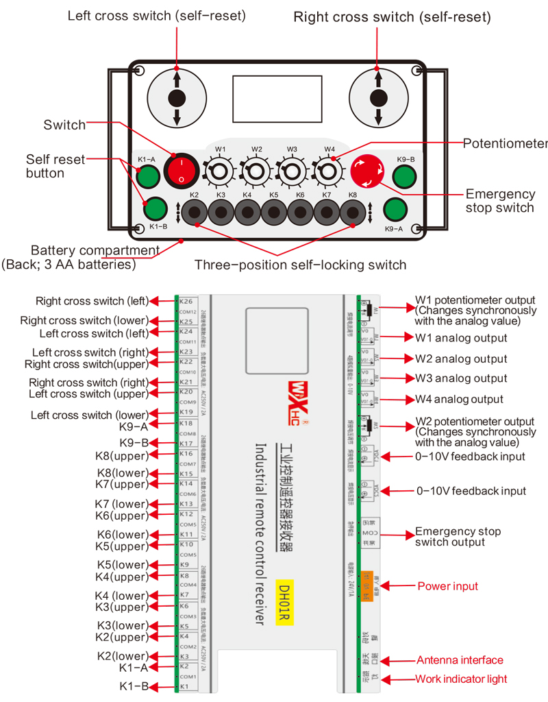
5.Beskrivning av fjärrkontrollomkopplare
6.Visa innehåll introduktion

W1 Knoppvärde: W1: 0-1000 (parameter justerbar 0-9999)
W2 Knoppvärde: W2: 0-5000 (parameter justerbar 0-9999)
W3 Knoppvärde: W3: 0-5000 (parameter justerbar 0-9999)
W4 Knoppvärde: W4: 0-5000 (parameter justerbar 0-9999)
ADC1 feedback display: 0-1000 (parameter justerbar 0-5000)
ADC2 feedback display: 0-1000 (parameter justerbar 0-5000)

Lågspänning: Fjärrkontrollbatteriet är för lågt, Byt ut batteriet.

Nätverk tappat: Den trådlösa signalen avbryts. Kontrollera mottagarens kraft, Slå på det igen, och starta om fjärrkontrollen.
7.Fjärrkontrollfunktionsoperationsinstruktioner
1) Slå på fjärrkontrollen
När mottagaren är påslagen, Mottagarens arbetsindikator blinkar; Installera två AA -batterier i fjärrkontrollen, Slå på strömbrytaren, och skärmen visar ett värde,indikerar framgångsrik start. Mottagaren som arbetar indikatorlampan blir solid.
2) Switch och knappfunktioner
Varje drift av vridningsomkopplaren och knappen på fjärrkontrollen kan styra motsvarande switch -signalutgångspunkt på mottagaren. Alla switch signalutgångspunkter på mottagaren är normalt öppna signaler som standard;
3) W1-W4-hastighetsjustering
Rotera knopparna i W1-W4 godtyckligt för att använda motsvarande analoga utsignal eller potentiometer signal vid mottagarens slut. Den analoga utgångssignalen vid mottagarens slut är standard för en 0-10V spänningssignal, och Potentiometer Signal är standard till 0-5K;
4) Emergency Stop Function
När nödstoppsknappen trycks in, Alla switch -signalutgångar är frånkopplade och den analoga utgången är frånkopplad; Efter att nödstoppet släpps, Alla switch -signaler återställs och den analoga utgången återställs; 5 sekunder efter att fjärrkontrollen har stängts av, Alla switch -signalutgångar är frånkopplade och de analoga mängderna förblir oförändrade. När fjärrkontrollen är på, Switch -signalen matas ut automatiskt återhämtar sig automatiskt;
5) Parametermeny (Användare är förbjudna att ändra det privat)
Vissa funktioner i fjärrkontrollen kan justeras via parametrar. När displayen w1 = 0, Tryck på K9-B-knappen 3 tider i rad, och tryck sedan på K9-A-knappen 3 gånger i rad för att ange parametermenyn; K9-A och K9-B-nyckeln till sidan genom menyn och välj Parametrar; Håll ner K1-A, och tryck sedan på K9-A/B-knappen för att ändra parametrar;
Avsluta parametermenyn: Välj att spara eller inte spara, och tryck sedan på K1-A-knappen för att bekräfta utgången;
F1W1 -intervall: Displayområdet för W1 -ratten på skärmens skärm på skärmen, justerbar från 0 till 9999;
F2W2 -intervall: Displayområdet för W2 -ratten på skärmens skärm på skärmen, justerbar från 0 till 9999;
F3W3 -intervall: Displayområdet för W3 -ratten på skärmens skärm på skärmen, justerbar från 0 till 9999;
F4W4 -sortiment: Displayområdet för W4 -ratten på skärmens skärm på skärmen, justerbar från 0 till 9999
F5A1 -intervall: Visa ADC1 Feedback Display Range Value, 0-5000 justerbar;
F6A2: Visa ADC2 Feedback Display Range Value, 0-5000 justerbar;
Larmström: Ställ in larmvärdet för ADC1 och ADC2 Feedback Display. När ADC1 och ADC2 överstiger detta värde, Fjärrkontrolldisplayen kommer att larma; När detta värde är 0 är larmfunktionen ogiltig;
8.Fjärrkontroll elektriska egenskaper

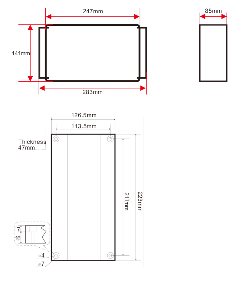
9.Fjärrkontrollstorlek
Den slutliga tolkningsrätten för denna produkt tillhör bara vårt företag.
