Descrizzione
1.Introduzione di u Produttu
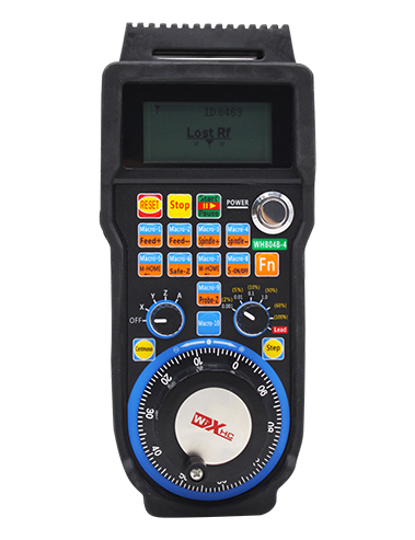
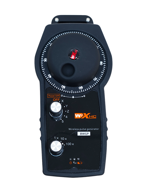
Wireless electronic handwheel is used for manual guidance, Pusizionamentu, tool setting and
other operations of CNC machine tools. Stu pruduttu adopts tecnulugia di trasmissione wireless,
eliminating the traditional spring wire connection, riduzzione fallimenti di equipaggiu causati da cavi,
eliminating the disadvantages of cable dragging, oil stains, etc., and is more convenient to
operate. It is widely used in CNC machine tools such as gantry machining centers, gantry
vertical lathes, CNC gear processing machines, and can be adapted to a variety of CNC
systems on the market, cum'è siemens, Mitsubissi, Fanuc, syntec and other CNC system
brands.
2.Product features
1. Adopt 433MHZ Tecnulugia di cumunicazione wireless, A distanza di operazione wireless hè 80 metri;
2. Adopt automatic frequency hopping function, use 32 sets of wireless remote controllers at the
same time without affecting each other;
3. Sostenite u buttone di stop di emergenza, and after the handwheel is turned off, the emergency stop
button is still valid;
4. SUPPORTATU 6 buttone persunalizati, Switch io segnale output;
5. Supportu à u cuntrollu 6-axis, 7-12 U cuntrollu Axis pò esse persunalizatu;
6. Supporta 1x,10X, 100X Control è pò esse massimu di 1000x persunalizabili;
7. Supports the enable button function, output switch l0 sianals. selezzione di l'assi,maanification
and encoder.;
8. Support axis selection and magnification selection encoder output;
9. Support standard Type-C charging, 5V-2A charging specification, built-in battery specification
14500/1100mAh.
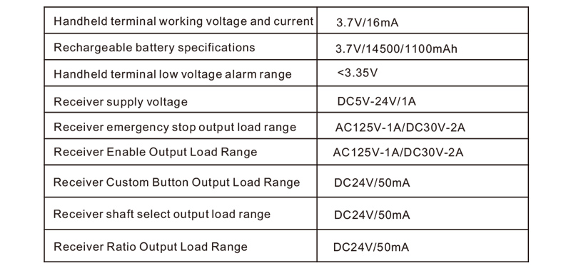
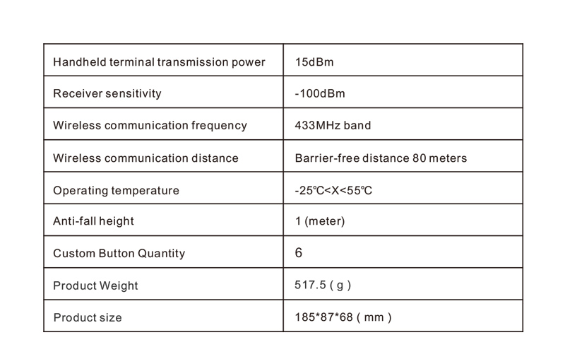
3.Specificazioni di u Produttu
4.Product function introduction
Note:
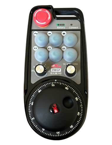
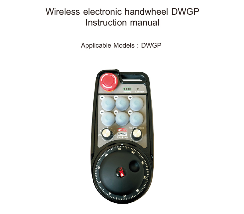
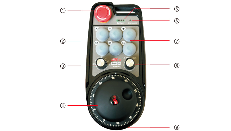
①Emergency stop button:
Quandu u buttone di stop d'emergenza hè pressatu, the two emergency stop IO outputs on
the receiver are disconnected, and all handwheel functions are invalid. When the emergency
stop is released, the emergency stop IO output on the receiver is closed, and all handwheel
functions are restored; and after the handwheel is turned off, the emergency stop IO output
of the receiver is still valid when the emergency stop button is pressed.
②Enable button:
Press any one of the enable buttons on both sides, and the two groups of enable IO
outputs on the receiver will be turned on. Release the enable button and the enable IO
output will be turned off. In più, you need to press and hold the enable button before
switching the axis selection ratio and shaking the handwheel. This function can be
canceled through the configuration software.
③Axis selection switch (Swack di potenza):
Press and hold the enable button and switch the axis selection switch to switch the
moving axis controlled by the handwheel. Switch this switch from OFF to any axis and
turn on the handwheel power.
④Pulse encoder:
Press and hold the enable button and shake the pulse encoder to send out a pulse
signal to control the movement of the machine axis.
⑤Battery indicator:
The hand wheel power display, all bright means full power, all off means it is not
turned on or has no power, the first left grid flashes, indicating that the power is too low,
please charge in time.
⑥Signal Lights:
If the signal light is on, it means the handwheel is being operated and the signal is
normal; if the signal light is off, it means there is no operation, or it is being operated but
the wireless signal is not connected.
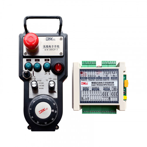
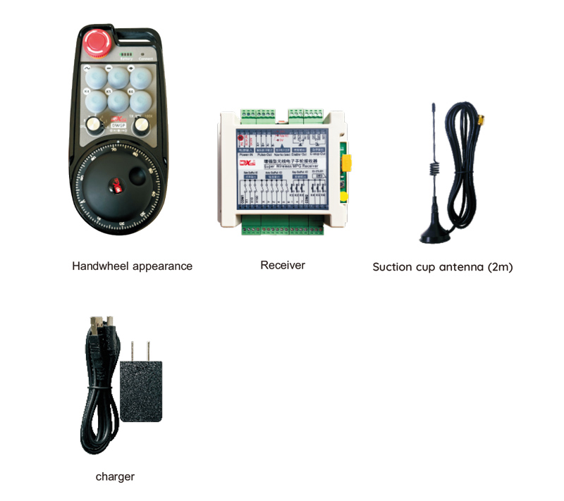
5.Schema di l'accessori di u produttu
6.Guida di installazione di u produttu
6.1 Product Installation Steps
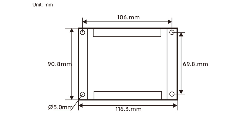
1. Install the receiver in the electrical cabinet using the clips on the back, or install it in
the electrical cabinet using the screw holes at the four corners of the receiver.
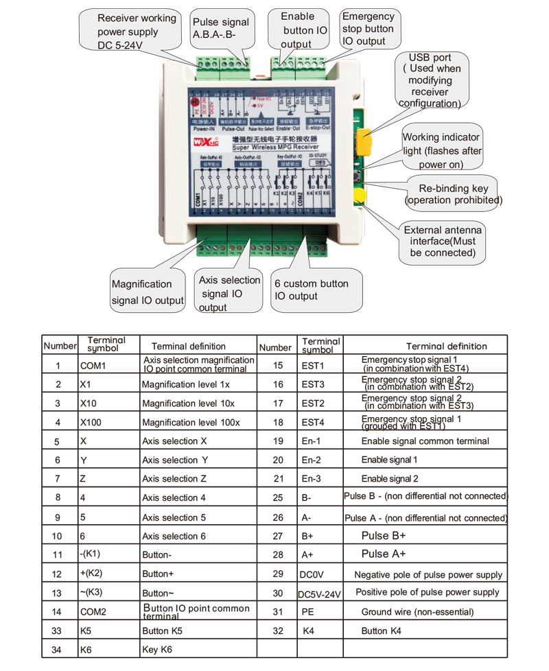
2.Refer to our receiver wiring diagram, compare it with your on-site equipment, and connect
the equipment to the receiver via cables.
3.After the receiver is fixed, L'antenna equipata da u ricevitore deve esse cunnessu,
and the outer end of the antenna must be installed or placed outside the electrical cabinet. It
is recommended to place it on the top of the electrical cabinet for the best signal effect. It is
forbidden to leave the antenna unconnected or place the antenna inside the electrical cabinet,
which may cause the signal to be unusable.
4. Finalmente, turn on the handwheel power switch and you can operate the machine by
handwheel remote control.
6.2 Dimensioni di installazione di ricevitore
6.3 Diractu di Referenza Ricevitore
7.Product Operation Instructions
1. The machine is powered on, the receiver is powered on, the receiver working indicator
light flashes, the wireless electronic handwheel has the battery installed, the battery cover
is fastened, the wireless electronic handwheel power switch is turned on, and the
handwheel power light is on;
2. Selezziunate l'assi di coordenate: Pulse è mantene u buttone Attiva, switch the axis selection
cambià, and select the axis you want to operate on;
3. Selezziunate ingrandimentu: Pulse è mantene u buttone Attiva, switch the magnification switch,
and select the magnification level you need;
4. Assi muvimenti: Pulse è mantene u buttone Attiva, Selezziunate u switch di selezzione Axis, selezziunate
the magnification switch, and then rotatethe pulse encoder to rotate the positive moving axis
clockwise and the negative moving axis counterclockwise;
5. Pulse è tene qualchì buttone persunalizatu, and the corresponding button IO output of the
receiver will be turned on. Release the button to turn off the output;
6. Pulse u buttone di stop d'emergenza, the corresponding emergency stop IO output of the
receiver is disconnected, the handwheel function is disabled, release the emergency stop
button, the emergency stop IO output is closed, and the handwheel function is restored;
7. Se a manu ùn hè micca operata per un periodu di tempu, it will automatically enter sleep
mode to reduce power consumption. Quandu hè adupratu di novu, the handwheel can be
activated by pressing the enable button;
8. Se a manu ùn hè micca aduprata per un bellu pezzu,it is recommended to switch the handwheel
shaft to the OFF position, Apaga u putere di manu, è allargà a vita di a bateria.
8.Descrizzione di u mudellu di produttu

① :DWGP represents the appearance style
② :Parametri di i pulizia:
01: Indicates that the pulse output signals are A and B, and the pulse voltage is 5V; Pulse
quantity 100PPR;
02: Indicates that the pulse output signals are A and B, and the pulse voltage is 12V; Pulse
quantity 25PPR;
03: Indicates that the pulse output signal is A B、A-、B-; Tecnula di fiorsa 5v; Pulse quantity 1
00PPR;
04: Indica un output di circuitu di circuitu apertu di u livellu di livellu npn, cù segni di pruduzzione pulse di A è B; lu
number of pulses is 100PPR;05: Indica un output di fonte di altu livellu pnp, pulse output signals
are A and B; pulse quantity is 100PPR;
③ : represents the number of axis selection switches, 6 rapprisenta 6 assi, 7 rapprisenta 7 assi.
④ : represents the type of axis selection switch signal, Un segnu di outtu rappresentanu di punta,
B represents encoded output signal;
⑤ : represents the type of magnification switch signal,
Un segnu di outtu rappresentanu di punta, B represents encoded output signal;
⑥ : represents the number of custom buttons, 6 rapprisenta 6 buttone persunalizati;
⑦ : represents the power supply for the system handwheel, 05 rapprisenta a supermia di u putere di 5v,
è 24 represents 24V power supply.
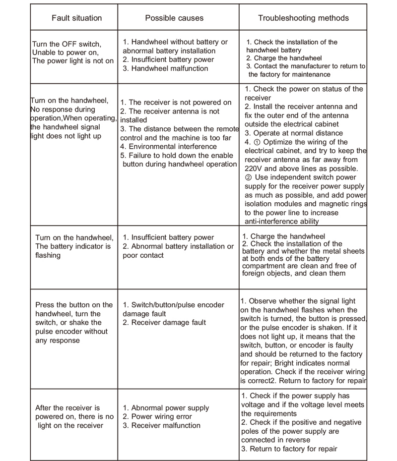
9.Product Troubleshooting
10. Maintenance and care
1. Aduprate lu in un ambiente seccu à a temperatura è a pressione di l'ambienti per allargà a so vita di serviziu;
2. Per piacè evitate d'utilizà in ambienti anormali cum'è a pioggia è e bolle d'acqua per allargà a vita di serviziu;
3. Per piacè guardà l'apparenza di a manu pulita per allargà a so vita di serviziu;
4. Per piacè evitate di sbulicà, Caduta, BUMPING, ecc. to prevent damage to the precision components inside
the handwheel or accuracy errors;
5. Se ùn hè micca usatu per un bellu pezzu, Per piacè guardate u maghju in un locu pulitu è sicuru;
6.Durante u almacenamentu è u trasportu, L'attenzione deve esse pagata à a resistenza di umidità è di scossa.
11.Infurmazione di sicurità
1. Leghjite puru i struzzioni prima di utilizà è pruibisce micca i prufessiunali di l'operazione;
2. When the battery level is too low, please charge it in time to avoid errors caused by insufficient
battery and inability to operate the handwheel;
3. Se hè necessariu a riparazione, per piacè cuntattate u fabricatore. Se u dannu hè causatu da a riparazione di sè stessu, U fabricatore ùn furnisce micca guaranzia.
